![]() Builders Forum
Builders Forum
Look for the ![]() sign to
see new stuff
sign to
see new stuff
Note: The information this forum provides is given in good faith, and is based on the knowledge and experience of amateur Jabiru builders. We try hard to avoid 'contentious' issues or any advice which could adversely affect the specification of the Jabiru aircraft or engine, their operating characteristics or performance. Ultimately, the standards of workmanship and any modifications are subject to the scrutiny of The Popular Flying Association (in UK), their network of skilled Inspectors, and equivalent international advisory and legislative bodies, as well as the manufacturer, Jabiru Aircraft Pty. and the (UK) importer, ST Aviation.
In Australia Mods can only be done to AUF or SAAA Amateur built, not factory built or 101.28 built
Although most of this information is based on the two seat Jab - SK,SP,SPL,UL, some of it also applies to the Calypso, J400, J450 and J430 types
Note : there is a chance that some of the information given is out of date as kits are updated and modified by the manufacturer
Topic |
|
Email your ideas to me to be included on this page (pictures where possible)
The linked text will take you to a picture or web site relevant to the text. Use page back to return to this page
Contributed By: |
|
| During the interminable weeks of waiting while your kit is shipped (!), get as
much preparation done as possible, so that you can get into the build soon after delivery.
If possible, try to get your build manual early and familiarise yourself with the
contents. As for your workshop, give it a good clean - out and if you can, upgrade the
lighting and power with plenty of strip - lights and extra sockets for power tools. Also,
paint the walls and ceiling white to provide as light an area as possible. This will
definitely help if you plan to prepare the aircraft for painting (filling / primer ) and
also the top - coat if you are capable. If you are building in the UK during winter, some
extra heating and insulation in your workshop will help, too, as well as keeping the
humidity levels up to acceptable levels for epoxy work. Clearly, all workshops are
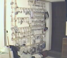
different and your build inspector will advise. Get a large roll of bubble - wrap packaging sheet (1.5m x 15m) from your local garden centre or packaging company (cheaper). In low temperatures, you'll use this to create an insulated 'tunnel' by draping it over the work you've bonded / flocked and, with the careful application of warm air from a fan - heater, you'll easily achieve the 20�C (or so) you need for a good epoxy cure. In preparation for lots of bags of small parts, construct a 'wall-board' to which you can pin / hook the bags, in the order of build sequence. For the larger, bulky items, prepare as much shelf - space as you can and also some shelf - brackets (only) in pairs to rest long items like elevator, flaps, etc until you need them. Doors can also be hung on these. Keep an out-of-the-way area clear for windows and other fragile parts Some builders are choosing to have all their aluminium parts anodised in a colour of their choice when the kit arrives. (I didn't, but I admit it does look good!). Bear in mind that some parts will require small 'adjustments' which may mean re-anodising afterwards. If you prefer the natural look, you can get a nice 'brushed' finish by rubbing with a ScotchBrite abrasive pad. Try different grades on bits of scrap metal first. If you're going to do any painting, try to keep as much off the floor as possible, so that you can vacuum / sweep the place out thoroughly to minimise dust before the job. I found it helpful to hose - out the workshop floor at this stage! It's a good idea to get extra insurance for your kit during the build, to cover any risks (fire / damage / theft, etc). Most aircraft insurers will quote and (having spent all that money on the kit) it's worth - it for the 'peace of mind'. |
Andy Silvester |
| The list of tools shown at the beginning of the manual is the bare minimum
needed. We've found the following items essential additions: Electric hot air (paint stripping) gun - used to 'adjust' some non - structural GRP (Glass fibre) airframe parts, like doorframes, door stop strip, etc. Also top of windscreen - with care! Electric Angle - Grinder (4 - 5") - this is for grinding some parts for better fit, like the window edges to fit the rebates. If you can get an adjustable - speed one, so much the better. Fit a disc sander backing pad and use discs between 80 and 240 grit. Torque wrench for engine / prop fitting, etc. Check the torque settings in the Technical Manual to ensure you get one with the right range. 3 or 4 straight lengths of (e.g.) 20x20x3 x 2m aluminium angle (or channel) for setting the position of the tailplane / fin relative to the 'datum of the lower and rear door - frames. Clamp the angle across fuselage to lower door frame, then it's easy to 'eye' up the tailplane from the rear with reference to it. Clamp the angle to the rear inside of the frame, and use tape measure(s) to check that the tailplane is 'square' in its mount while screwing / gluing. The following tools aren't essential, but they certainly make the job easier!: Cordless Screwdriver with various bits (get some spare Phillips #2 bits: those self - tappers are hard!) Permagrit abrasive tools for shaping / sanding GRP parts (try to get a set of various shapes, including a 600mm long coarse / fine 'block' - very useful for straight edges, like trailing edges, etc. - See their web site. Electric Orbital Sander for surfacing filler . Electric Jig Saw for cutting wing T/E for aileron / flap fitting, and other holes in wing / fuselage. Digital Kitchen Scales (5kg max) for mixing resins by weight, using the mixing pots provided. Accurate measurements of small mixes can be made, and you don't have to spend time making the scale shown in the manual! These scales can be bought at Argos in UK. Dremel Moto - Tool (cordless and multi - speed if possible) - used for grinding / drilling GRP in hard-to-get places. Permagrit make some very useful bits for these; the cut - off disc and cylindrical grinding tools are particularly useful. Air Compressor & blow gun. You can probably do without this if you 'contract - out' your filling and painting job, but if you intend to prime / fill / paint, you'll definitely need to use the blow - gun (nozzle) to clean - out crevices and pin - holes in the gel - coat. If you intend to do all the painting, get a good spray gun and a compressor capable of 15cfm, and don't forget a good mask and protective clothing! You'll probably know this, but DO NOT attempt to spray 2 - pack (isocyanate) paints unless you have a specialised Air - Fed mask. Vacuum cleaner with 'crevice tools' You'd be surprised how difficult it is to get GRP dust out from behind the seats with a brush! Also, you'll have loads of GRP 'dust' around after shaping parts and this is dangerous stuff if breathed - in. If you don't want to fall - out (further?) with 'Her Indoors', don't use the house vacuum cleaner! |
Andy Silvester |
| There are some items called for in the construction manual -- There are some items called for in the construction manual that some people (including me) have had problems sourcing. Item Description RS Part Number Size Price Loctite Bearing Fit 641 RS 514-559 10ml � 4.93 Loctite Prism 480 (Rubber Toughen Cyanacrylate) RS 514-593 20gm �16.63 Loctite Superlube (Rubber Grease) RS 184-7967 85gm � 4.74 RS Anti-Seize Compound RS 557-073 50ml � 1.80 RS Webb site rswww.com I found RS to be VERY effecient - orders are delivered the next day. |
Edmund Comber |
| I have been using some aluminum tee section ( 40 X 40 ) for straight edges and I have found its a very good way of getting accurate edges . The tee section also allows for some special tools to be made .I use a thin double sided Sellotape (about the thickness of conventional Sellotape ) and the sandpaper is stuck to that . The same system is used on small hand tools and works quite well . The double sided tape can be easily removed from the section as it sticks to the sandpaper , so replacement is quite easy . I bought one long section and cut it into various lengths . Just select a " straight " section at your local hardware shop ( place one section against the other to check for straightness ). | Mike Muller |
| SPECIAL TOOLS Dremel grinder is a must, get a carbide arbor and 402/426 abrasive wheel. Jigsaw, preferably electronic speed control. Orbital sander with vacuum. The aircraft can be mounted like a pig on a spit. Go to a place that fits exhaust systems. Buy a piece of steel tube with a right angle bend, to fit through the noseleg bearings and stay it (use flat steel) to the top motor mount holes, so it can't move from side to side. Fit a length of square steel tube into the U section at the rear of the horizontal stabilizer. Weld half hinges to it so you can pin the tube to the elevator hinges. Weld a round steel tube to the square tube so it projects straight out the back. Stay it up to the rear of the fin with flat steel. Rest the front and rear shafts projecting out either end of the fuselage on high trestles. You can now roll the aircraft fuselage to any position, even upside down. Two ropes from the wing tabs to ceiling hooks will stabilise. |
Andy Hollit OZ |
| NUTS AND BOLTS AN3 max torque 25 inch pounds, AN4 max 66 inch pounds, AN5 138 inch pounds.Wooden prop, torque to 6ftlbs Check torque summer & winter as wood swells with humidity. |
Andy Hollit OZ |
| Weight and Balance calculator Jabiru SK | Andy Hollit |
| Ever been distracted on take off, then wondered why cruise performance was so poor?
They go so much better with the flaps up! I mounted a door switch (try wreckers, electronic shops, burglar alarm shops) in the top indent hole. With no flaps, the button is depressed. When you move to first or second stage the switch closes and activates a flashing red jumbo LED on the panel. Also reminds you to retract flaps when taxiing. |
Andy Hollit OZ |
| ADHESIVES Bog; Polyester automotive bog doesn't stick well to either polyester or epoxy and in time it shrinks. It's also relatively heavy, so use epoxy bog. Poly Fibre filler is excellent, always the right consistancy or mix your own. I found West Systems epoxy 105 with 206 slow hardner was readily obtainable from boat shops. Mix in Qcell (Microballoons) so it's real thick and goop it on. I used a digital humidity measuring device, (available from electonic hobby shops), syringes from the chemist to transfer epoxy to plastic beer cups (from the supermarket), weighed on a balance as per the constructors manual, mixed and applied with tongue depressors (from the chemist). Sikaflex is a wonderful adhesive with many uses around the Jabiru; after all they use it to glue buses together! It is a polyurethane sealant adhesive which bonds but never hardens and never lets go. To get it apart, the trick is to use detergent on the knife blade. Unfortunately, once opened the whole cartridge goes off very quickly, keeping it in the fridge helps. |
Andy Hollit OZ |
| DRAIN/AIR HOLES REQUIRED Bottom of rudder. Elevator tips. Aileron tips. Under master cylinder. Door bottoms. Sound curtain/floor. Tail cone before cross brace. Rear of passenger & pilot floors. Keel fin. |
Andy Hollit OZ |
| FUEL SYSTEM Leave the tank unpainted but glue fabric to the top of the tank to protect it from luggage. Leave a hole in the fabric near the inlet to check the fuel level when filling the tank. Don't let the fuel inlet support the weight of the fuel pump nozzle or it will crack. Instal a rubber grommet where the fuel tubing exits the centre console. An earthing wire must run from the tank earth back to the console earth buss. Replace the fuel tubing with high quality, blue fabric covered line (Aeroquip 8346 2705). For security, replace threaded swivel on fuel cap with a nylock nut. Carry a tube spanner. To prevent fuel loss on takeoff, remove the aluminium vent tube (hot iron) and cut off the fibreglass tab. Cut out a 50mm straight section and epoxy it in the tank, vertical. Run the vent tube straight up, around window and down to a 90 degree exit pipe (cut from the vent tube). You can't see the fuel level below 30 litres. Auto instruments (83624881) have a magnetic fuel float moving on an enclosed reed switch. Epoxy the shaft in an aluminium tube mounted vertically on a double flange set 100mm starboard of the filler. Set height for 10 litres. I velcro'd an acrylic mirror (with a 30mm hole in the centre) to the hole in the fuselage former. This enables me to see the fuel level when it gets below 20 litres (and is an excellent signaling mirror!). A 50W lamp mounted in a holder, epoxied to the back of the fuel tank, lights it up, making fuel levels much easier to see. You don't have the light on for long. I used a starter pushbutton switch and mounted it to the right of the throttle. N.B (NEARLY CAUSED A FIRE ON ONE IN THE UK if you use Avgas and don't paint the tank, you can see the fuel - Vic) Using a 90 degree barb on the inlet side of the boost pump makes routing fuel lines easier. There are high pressure and there are low pressure boost pumps; and they appear identical. The Jabiru uses low pressure, the local auto parts supplier has high pressure! The use of teflon tape to seal fuel connections is not acceptable in aircraft, as re-fitting can allow bits of teflon to block fuel flow (and has!). Loctite make a thread sealing compound designed for fuel fittings. The brass fuel inlet barb to the carby just sits in place with an O-ring. The whole thing came out when I was trying to pull the fuel line off, so I epoxied it in place. |
Andy Hollit OZ |
| Enlarge the slot in the fibreglass center tunnel where the elevator control rod passes through and attaches to the control column. Check clearance in the full up and down in both full left and right stick positions. Sufficient clearance is required to prevent side-bending loads on the end of the control cable. | Vic Leggott |
| When assembling the nose leg, substitute the suspension rubbers with an approx. 4-inch
length of 1-inch dia. aluminum tube. It is much easier to fit the suspension rubber stack
after the engine is installed. With the front wheel chocked use the weight of the engine
and a bit more to compress the rubbers before fitting the top retaining collar and bolt.
Kits are now supplied with a one piece pre assembled yellow polypropylene stack with one
black rubber on the top. It may be necessary to put an extra rubber in the front
suspension rubber spacer set. The rubbers can vary in density so you might have a squashy
set making the suspension too soft. You should have a couple of spare rubbers used in
packaging the engine! See above (new part). The above mainly applies to early planes. With the new yellow rubbers and especially the Red nose leg rubbers eg J160/J400 etc. You will need to compress the rubbers off the plane using long levers |
Vic Leggott |
| Place saw cuts in the curved shell of the flap handle between the pivot bolt and the locating spigot to allow the handle to flex in operation, which means the pivot bolt can be tightened which reduces the amount of play on the flaps themselves. | Vic Leggott |
| Make sure rod ends are locked in the correct orientation at each end allowing maximum rotation and so preventing side loads on the threads. | Vic Leggott |
| PREPARE & PAINT AIRFRAME Pinholes. Hit the entire airframe with a stainless steel
wire brush to break through pinholes; (not such a good idea if you want to avoid hours
of filling unessessarily revealed pin holes- Vic Leggott) or move along the surface
with a hot air gun (unsuported gelcoat will sag). Holding parts against a bright light
(1,000W) will also reveal pinholes. Fill pinholes and contours with epoxy bog. A piece of
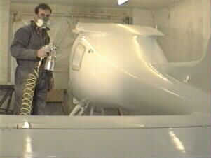
plastic 90mm water pipe makes a good sanding 'block' for in front of the windscreen. Polyfibre Smooth Prime is an excellent primer (although the hardner has a very limited shelf life). Lightweight, good adhesion and safe to use. Roll it on, then sand it off. Go down to 320/400 using an orbital sander with a vacuum system (borrow the wife's Electrolux!). Round all fibreglass edges, as paint doesn't bond well to a sharp edge. Don't go too fine if using 2 pack as it needs something to 'key' in to, 400 grit is fine, as the paint is quite viscous. Mask first with 3M Fine Line 218 to prevent paint creeping under, then masking tape on top. Use butchers paper, newspaper is small, has perforations and leaves ink on white surfaces. Remove masking ASAP as hard paint fractures as you peel it off. Don't use thinners or citrus based cleaners on acrylic windows as they will craze the plastic later. Don't use straight metho on the acrylic as differential cooling may cause cracking. Don't use paper towels or rags containing silicon or the paint won't bond afterwards. Before spraying, remove all marks made by pencil, felt pen, chalk, etc to prevent bleed through. Before spraying, blow out and vacuum fuselage and floor as blast from the gun will blow dust around. Before spraying, damp driveway/floor area to settle dust. Which paint system? My opinion only!! 1. Two pack isocyanate paints give a superb finish, tough and easy to apply; but MUST be used with an air fed respirator (the mask filters available are designed for use in a spray booth where there is a constant flow of air, not the shed!) and suit. I used a cheap High Volume Low Pressure (HVLP) gun and the biggest compressor to run off single phase. Put the compressor where it can't ingest the spray fumes!! You will need a water trap and an oil trap in the respirator line and a water trap in the line for the gun. Isocyanates produce an alergic reaction, rather than a poison/cancer outcome. 2. Automotive acrylic is cheap, easy to apply, safe (in a ventilated area and with the right mask!) and very presentable. 3. Water based 2 packs I tried but couldn't get along with, wanted to run and produced a soft finish, not hard like 2 pack, more like vinyl house paint. Spraying 2 Pack. Terminology! There's a 'mist coat' (which just dusts the surface) then a 'heavy mist coat'. Next is a 'just wet coat' (where there's enough paint for it to flow out), then there's a 'heavy wet coat' (dangerous because you're on the verge of running). Never paint vertical if you can paint horizontal! Start with edges. First coat mist coat. Wait for it to 'dry' (15 min). This gives the wet coat something to grip, lessening the chance of running. Follow with 3 just wet coats, 15 minutes apart. Use strong lights to view progress. Leave for 5 days to harden. Resting on a newly painted surface will mar the finish. Rub back with 400, 800, 1200, 1500 wet. Use a rubber sanding block, sand with a crosshatch pattern, not around in circles. Polish with 'Farecla G3' by hand (much better 'feel' than with a buff. Use lots of water. |
Andy Hollit OZ |
| 1. Halfords ( UK ) sell a long 11mm socket for less than �3.00 which fits
neatly down the tube in the engine mount.You need a socket which is less than 16mm O/D -
this ones about 15.7mm and just fits. Also the shoulder on it is just far enough back to
fit the length of the tube. Halfords also do a 7/16 socket but its part of a set costing about fifteen pounds - better to go for the 11mm ! 2. I also have a drawing for a radio mount to fit the Icom A200 underneath the standard panel if anyone is interested. |
Alan Gornall |
| Factory black felt pen markings While building the fuselage I was very suspicious of factory marked holes and cut outs,checking them meticulously, and even then cutting undersize. As the fuselage got to completion I began to have much more faith in factory markings. THIS WAS A MISTAKE when starting on the second wing, I turned it upside down on the bench cut out the inspection hole and immediately drilled the 38 mm hole marked in black felt pen. Guess what! It was on the outboard of the inspection hole but never the less very clearly marked. Allright perhaps due to the accuracy of all the other marks I had grown complacent, but it was such an easy mistake to make. (As above) I too have found markings to be in the wrong place - i.e aileron cable hole in wing top surface - 1/2" too far outboard also 1/2" too far inboard! |
Derek Alan Izod Vic Leggott |
| When the kit arrives, probably two large crates and the engine box if you ordered it at the outset), you can exercise your electric screwdriver by removing the many screws holding the crates together. Kits are now delivery with a HiAb truck. It's a good idea to unpack and check the condition of EVERYTHING for transit damage etc, and then to loosely re-pack items not needed for a while, back in their bubble - wrap for protection. I . At this stage, I recommend spending as much time as is needed to check all items off against the packing sheets. If, as is possible, there are some parts missing, now's the time to get them ordered so that you're not held-up in the build. | |
| Epoxy Resins: This seems pretty obvious, but I think everyone I've known who is
'building' has suffered skin irritation at some time or other (some much worse than
others), so get some thin rubber - gloves and WEAR THEM when you are working with epoxy
resin. I went thro' a few pairs of washing - up gloves but I've heard that, if you can get
them, disposable surgical gloves are better. Gloves get very messy, so to be able to throw
them away rather than try to clean them with thinners is preferred! The epoxy hardener
also gives off fumes, so if you are working in a reasonably confined space, wear your dust
or paint mask too. GRP dust: It's likely when you're shaping / gluing / finishing GRP parts that (unless you vacuum - up after every operation) that the air will contain very small glass particles which if breathed - in, are dangerous to the respiratory system. In fact, the particle size can be about the same as asbestos and you know what that means! So, if you don't want to spend time recovering from a '40 - a - day cough' (or worse), WEAR AT LEAST A DISPOSABLE PAPER MASK, and use your vacuum cleaner to clean - up frequently. Paint (primer & top coat): Pretty obvious, but try to get as good a fume / particle mask as you can reasonably afford, Vic and I used ones with dual carbon filters (for the paint fumes) with disposable outer filters (for the paint mist itself) made by 3M and costing about �40 each. A good mask (like these) will mean that you can't even smell the paint thro' it while spraying. |
Andy Silvester |
| J160 vertical and horizontal stabilizer
There is no longer a requirement to add the glass reinforcing to the sides of the vertical fin to fuse join. There is now an extension that is fitted into the fin post. You still glass the fin post to the fuselage though. |
Vic Leggott |
| Try to get the gaps between control and fixed surfaces as small as possible; this cuts
down drag and looks better. Use a long Permagrit block, (or abrasive paper glued to a
straight-edge) to get the join edges straight. At this stage, find the control surface deflection templates, and use them to judge the smallest hinge gap
when the surface is at full - travel. Using clecos or nuts and bolts thro' the first
(undersize) drilled hinge holes will aid adjustment, then you can finally drill in-situ
for the rivets. If the thickness of (e.g.) the edge for the rudder hinge is different than
the adjacent edge on the fin, you'll get a 'step' between the two when finished, so
pre-fit the surface with clecos, or nuts / bolts and make a packing - piece for the
'thin' side to bring the surfaces flush. It's attention to these small points that will
make the difference in look and performance at the end of the job. On the rudder, bear in mind that the angle of
the hinge in relation to the fin means that the gap closes at the top of the rudder when
moved right to full - travel. You'll therefore have to aim for a small clearance between
the fin and rudder at full - right. You may want to fit a strobe at the top of the fin later, so you'll need to drill a hole at the chosen position, and run - in a suitable draw - string. To keep the run for the strobe lamp cable as far forward in the inside of the fin as possible (to minimise any interference with the VHF aerial at the back of the fin-post), Vic and I glued a couple of fairlead - rings inside the fin leading-edge. These were simply 5mm lengths of 18mm plastic pipe, glues with 5 - minute epoxy. To get the static - pipe and plastic tube threaded into the front - top of the fin, you'll have to drill an oversized hole ( about 12mm), then 'plug' it with 5 - minute epoxy / flock. Don't try to finish the job in one go; set the tube in place first, get it straight with the centreline of the fin, etc, then when reasonably 'set', mix some more and do the 'bullet nose' as per the manual. I suggest you fit and glue the elevator (weighted) end-caps before the stabiliser end caps. Fit the elevator hinges first, then fit the end caps to give a small clearance with the ends of the stabiliser. Now, fit the stabiliser end-caps to be flush with the ends of the elevator ends. |
Andy Silvester |
| KEEL Flock an aluminium eye into the keel fin to take tie down loads. |
Andy Hollit OZ |
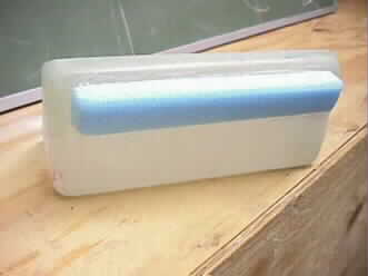
| J400 /J430 Fill the rear seat pan with foam
When you fill the rear seat pan with foam (Bostik) this might be helpful: a) Check the production date of your foam can Polyurethane foam has a very limited shelf life, approximately 12 month. It is very likely that your can has expired when you need it late in the construction process. The problem with too old foam seems to be that it will fail to expand to the same volume as new one. Therefore better buy new foam at your local DIY store. Any one component polyurethane foam will do. b) Buy at least 660ml, probably better 750ml. 500ml of foam will expand to 25l under ideal circumstances. The supplied 340ml (Bostik) can will therefore expand to about 17l. This might be enough for the seat pan but circumstances will be less than ideal. While filling up, the already filled in foam will create resistance (due to friction and pure mass) and immediately pressure will rise. Thus you'll not get the advertised expanded volume. c) Spraying some water into the cavity helps the expansion process. Drill 2 lots of three 10mm holes in a line under each bit where you would sit and squirt three big blobs each side and let them expand. Just scraping the excess off, that will force its way out of the holes, when it had cured. Be careful not to overdo it as the foam can carry on expanding for some time and push the seat up, creating a bulge
|
Mike Hermann |
Check out this Service bulletin from Jabiru regarding setting up elevator travel limits - you will need Adobe� Acrobat� Reader (its free) installed on your PC |
Vic Leggott |
| A number of people have asked me about the safety retaining lugs at the front of the
cowling on the two seat Jab. Later cowlings have hinge pins and fasteners Here are a couple of pictures showing how they should be fitted. The first one shows the lug riveted to the bottom cowl and where the slot has been made in the top cowl to receive it. The second pic shows it in place. The top cowl has to be pushed in at the front to release / insert the lugs in the slots. |
Vic Leggott |
When fitting the top and bottom cowl, to get a good join line, put a bead of filler on one edge and masking tape on the other then compress the two together. When set, clean up and do the same to the opposite surface. Ensure the aluminium retainers on the front of the lower cowl are fitted so that the hook faces in towards a slot that needs to be made in the front of the top cowl. (early two seaters) |
Vic Leggott |
| Before joining the top and bottom fuselage, trial fit it first. Check that the
top fuselage joint does not ride up over past the joggle - trim as required. Check
to see where the glass joining cloth will be and make sure that there is no paint on these
surfaces. Fuselage comes factory joined now! |
Vic Leggott |
| Perspex windows
When fitting the Perspex windows, produce a 'V' groove between the fiberglass and Perspex. Bevel the edge of the Perspex with an angle grinder fitted with a fine sanding disc and bevel the edge of the window recess. It is not necessary to use the screws and nuts to hold the windows in if using 24hr flock and resin. Still use the bolts/screws for the front screen though). Key the surface of the Perspex in the bonding area. Do not stress the Perspex while the resin is going off otherwise you'll get cracks. |
Vic Leggott |
| A number of builders are permanently bonding the gear leg speed fairings, with access doors for the strut bolts and gromets for the gear leg bolts. | Eric Bentley |
| Good old RS again, 549 937 and 549 921 Velcro strip for upholstry etc. I use it for fitting fairings under wing roots and lift struts, with a single self tapper at the leading edge to prevent the wind getting underneath. Also the hinged flaps on the lower lift strut fairings (folding wings only) | Alan Gornall |
| Ventral Fin (SK Only): Why not split the ventral fin into two parts, the
forward two-thirds bonded onto the lower fuselage and the rear third fitted to the
fuselage and the forward section with captive nuts. You will need to make a joggle -
joint beween the front and rear parts to fix the captive nuts. You should trial - fit the
ventral fin at the normal stage with screws in the front section and captive nuts at the
rear but Do Not bond the forward section until after the fuselage is joined. After
joining, the forward section can be faired into the fuselage. Aircraft come with this arrangement now - unlikely you'll be building an SK |
ST Aviation Vic Leggott |
| Sound Curtain Support (i): The sound curtain supports are no longer included in
the kit as the new doughnut bulkhead has taken its place. We still
use the sound curtain in the upholstery kit as we believe it is better to retain the sound
curtain to stop luggage moving too far aft. If you wish to use the sound curtain you will
need to make up some glass angle brackets by laying two layers of glass into a suitable
'L' shaped mould; just remember to wax the mould. Sound curatin now goes on the first bulkhead - no need for brackets 'L' shaped brackets (OLD SK Type) |
ST Aviation Vic Leggott |
| Throttle lever reinforcement: When doing some glasswork, lay a strip of two - inch glass inside the toolbox where the throttle lever bolts through. This will improve the smoothness of operation. | ST Aviation |
| Fuel Tap Installation: Make sure that the rotating barrel of the tap is screwed in fully and the lever is firm in operation with absolutely no looseness of the lever. If during installation the barrel is slightly unscrewed it will leak and this could really ruin your day. Check this each day you fly. | ST Aviation |
| FIREWALL Stainless steel firewall is now supplied with the kit |
VicLeggott |
| ACRYLIC WINDOWS Will crack when being drilled with a sharp drill, use a 6mm Unibit (Flintware). I found a countersinking bit with a single, sharp flange worked best. Don't drill acryllic when it's cold. To trim windows to size use a Dremmel with the abrasive wheel 426/402. Fit the curvy bits of the windscreen (at the top) first by using a hot air gun. |
Andy Hollit OZ |
| Windscreen fitting To avoid the risk of cracking the windscreen while countersinking the fixing holes, drill all the holes (carefully!) ensuring good support behind each hole, then fit the screen on a bed of 24h resin / flock (stiff mix) and fix temporarily using self - tapping screws. The screen MUST have been cut to shape and pre-fitted (using the hot - air gun to get the top corners to fit the recess) beforehand, and you'll need to roughen the back surface of the screen - edge to give a key to the flock. Use minimal effort to pull the screen onto the flock with the screws. You'll see the flock 'bed' thro' the edge of the screen and most of what you applied will squeeze out. Remove the surplus with a cellulose - thinners rag and leave to cure. Afterwards, remove the self - tappers carefully; then countersink the holes knowing that the screen is fully supported behind. You may have to re-drill the holes 4mm but again, this should be easier with the screen in situ. Ensure that each finished screw head is below the surface of the screen so that the subsequent filling covers them completely. |
Bernd Faupel / Andy Silvester |
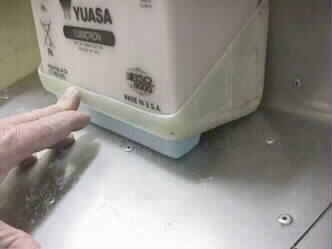
| I found the weight of the battery distorted the battery box . My freind David Paul came up with an idea of adding some foam and glass to the bottom of the battery box for support onto the firewall - works great .Also on my SP kit , the lower battery support simply rivets into the stainless steel firewall at the bottom with no ply support ( for some reason it not behind this point ) so I added a small support plate for strength. | Mike Muller |
| Use a small screw or Nut and Bolt to wirelock the fuel drain valve. - Careful you dont puncture the fuel tank ! | Alan Gornall |
| Electric flaps on Jabiru 450 UL click here | |
| J160 control column
The control column cross tube used to go out through the back of the seat cross member as on other models. Now the center tunnel doesn't go all the way back to the seat cross member and the output to the aileron cables is in front of the seats. |
Vic Leggott |
| Jabiru Roof Window - click for information | Vic |
| The VLA panel is an option
instead of the standard pod type or full width three part panel. When I installed my VLA panel I cut out big access holes either side on the top of the panel molding and cut out all of the front. I re-enforced the centre section and built a radio stack and also made a mold for my Garmin 295 to sit in behind the face plate. I made the face plates in four sections out of ali sheet and they are held in by rivnuts and counter sunk stainless screws. The plate made for the GPS is removable on its own to allow access to the unit. I cut out the sections on the lower part of the panel where the switches and fuses go and moved them forwards towards the front of the panel. Left where they are makes it difficult to see the switches when seated in the plane. This panel shape has been superseded. I can supply the new wide panel surrounds as fitted to the whole jab range http://www.vicdrive.co.uk/extras.html
|
Vic Leggott |
The old wide instrument panel comes in three sections. As supplied it is designed to hinge down either side of the centre section but I didn't see this as very satisfactory, I found it was more practical to join them together with rivets and flock to make a one piece unit, this means you can dispense with the brackets for the centre section. I chose to cut out the fibre glass fronts and replace with removeable aluminium panels for improved access. I customised the center section and fitted a transponder, garmin GPS90 and Icom A20 transciever. Andy has gone a step further and had the panel finished in leather with a transponder, Icom A200 radio and a Sky Map II GPS. |
Vic leggott |
| To save some swearing I recommend fitting the nose leg housing before finally fitting the rudder pedals - there is a nut and plate to be fitted at the front of the center tunnel behind the rudder pedal bars and access is difficult with the rudder pedals in place!! | Vic Leggott |
| Make sure you paint the windscreen/door pillar and the area in front of the roof cross beam prior to fitting the windscreen as once fitted it will be difficult to access. | Vic Leggott |
| When the top fuselage is bonded to the lower fuselage there will be excess material to
remove from around the door opening. Leave approx. 1/4 to give an edge to fill to when
setting the gap for the door opening, then trim as required. New kits have not got this
overhang and the doors fit a lot better. Kits now come with the fus join factory done! Two seat kits now have a pre molded door shut. |
Vic Leggott |
| It is not particularly clear from the manual and the shape of the throttle stop as to which way round to fit it - see diagram. | Vic Leggott |
| Make sure that S.T.Aviation part - ST001 (aileron control stop) is fitted as required by the PFA. They are simply two large nuts on top of the aileron control stop plate bolted from underneath as opposed to the supplied studs. This is to prevent the aileron drive plate on the end of the horizontal tube over running the stops. | Vic Leggott |
| I decided to fit submerged Naca air intakes in place of the air scoops for the interior ventilation. I made a mould out of wood after calculating the shape from a formula, according to the overall dimensions required. | Vic Leggott |
| Standard AIR VENTS Use the tab longways so it's easier to hook your toe on to it. Don't use 5 minute epoxy, weak.Epoxy brass flywire screen just inside the opening to prevent angry wasps in the cockpit! Stick velcro, 20mm long on the slides. The friction stops rattling and holds it in position. |
Andy Hollit OZ |
| RUDDER PEADALS When installing the rudder pedals, set the plastic bearing blocks on some resin flock and assemble the rudder bars on top in the correct position but do not tighten the bolts until resin has set. This means when the bolts are tightened, everything remains square. Without the flock, the blocks, when bolted down, will go out of alignment and make the rudder tight to operate. Some material may have to be removed from the inside surface of the bearing block. The rudder pedals should operate freely without any binding. |
Vic Leggott |
| CONTROLS Turn knobs from exotic timber eg. Blackwood or Teak (Otto's 8362 3522). Don't install the throttle on the passenger side, useless and can be knocked closed! Use the good epoxy for the fibreglass stops, 5 minute epoxy is too weak. Replace the green nylon throttle crosstube bearing blocks with black (Enzed 8268 7566). TRIM CABLE Use a rubber grommet where it exits the lower fuselage. Secure with superglue. Drill a hole in the brake master cylinder mounting plate, pass cable through a grommet. JOYSTICK ASSEMBLY Before flocking the bearings, set minimum end play and set the plate to hit the bolt head stops. Discard plastic top (they crack) and turn up an aluminium cap to take the PTT switch. Use a single wire triggering a relay for the radio. BRAKE CENTERING SPRING AND HORN To centre the spring in the console, make 2 aluminium spacers. Spring sits in the middle. Run the spring in a piece of irrigation poly tube to prevent chaffing the console. Hold aluminium actuating plates together with solid rivets, not pop rivets (Parts Network). BRAKE MASTER CYLINDER For easier removal, tap the aluminium mounting plate for the 2 bolts, screw them in from the blind side and epoxy the 2 bolt heads to secure. This provides 2 studs. Use locknuts to mount. Drill a hole in the mounting plate for the trim cable and grommet. FLAP ACTUATING HANDLE Is too stiff which bends the pivot bolt. Cut slits in the top cover to allow more flex. Also, cut out a triangular section from the thick baseplate, it's still very strong but can now flex. To avoid a hole, bolt on the locating knob with a nylock nut before joining the top and bottom. |
Andy Hollit OZ |
| As the builders forum advises , the throttle arm attachment points needs reinforcement
. I used some foam at the back and another "stauff " clamp from the factory to support the arm
closer to the actual cable pull point . I have found 1/2" Id plastic tube at my local hobby shop and used it to protect and support the Throttle and Rudder cable . It works great at any other point where the cables need to pass through a flat panel .They can be flocked in then two layers of light glass for strength . |
Mike Muller |
| Replace the elevator cable clamp SLR rivets just behind the control colmn with AN3 bolts as we have reports of the rivets loosening off. I am considering replacing the rudder clamp rivets on the beam with the same. | Geoff Hennig |
| (J4XX) It has been found to achieve the correct trim speed range and stability to meet FAR23, it is necessary to stretch the forward spring on the trim rod by about 2X. It is also necessary to cut out the shoulder in the forward nylon bush to allow it to slide all the way up the trim rod and not stop where the rod goes from flat to round. You still need a lip inside the bush to retain the spring. The position of the trim horn on the fuselage is critical. You want it so
that the pivot for the trim mechanism is in line below the clamp for the elevator cable.
Don't drill and fix the brackets for the trim cable until the elevator is fitted and you
can check to see the range of movement is correct |
Vic Leggott |
| This is a picture of a footplate. It allows the passenger to movetheir feet about, without fouling the rudder pedals. It's held in place with velcro and can be removed in flight if the passenger wants to 'steer' for a while. I stow a pack on the passenger floor when travelling by myself and the plate stops any rudder pedal interference, | Andy Hollit |
J400/J430 dual brakesThe inboard pad is riveted directly to the back plate. Make sure you have the back plate the correct way round. There is a chamfer on the inboard side axle hole to allow for the radius on the axle. I've made a tool out of a couple of bolts - one with a flat end to go up against the flat head of the rivet and the other one has a shape ground on the end like a golf tee. This splays the open end of the rivet before flattening out. If you just hit it with a hammer it will squash side ways or crack. The back plate uses slightly shorter rivets than the bar on the other side so make sure you get the correct ones. ( you must use the brass alloy rivets - I've seen people use pop rivets!) They drill out easily enough when requiring renewal. You still require the ali. Bracket for spat mounting Make sure you get the brake pistons the right way round i.e. flat side into the cylinder and open side out. See photos Dual brakes with quick remove pads The latest design is for the brake back plate to remain attached to the axle and gear leg and the wheel to stay on when you change the brake pads. There is now a stainless steel back platewith the pad on it, which goes between the old back plate and the disc. The old back plate has holes drilled to allow clearance on the brake pad rivet heads. Brake3 |
Vic Leggott |
| I live in South Africa and own a used ( 40hrs when purchased ) SP 2200 with a long range tank, taking 85 liters. Since I bought it, I was a bit worried as it tended to sit on it's tail very easily, specially with the tank full. After looking at my weight and balance sheet compared to others, I realized that my nosewheel is about 8-10 Kg less than most SP's. I then also measured the distance from the strut center and the axles and found that my wheels sit too much forward by 50MM. This caused quite some head scratching until I have realized that the builder has swopped the two gear legs around. Once they are painted, the marks are off I guess. We swopped it around and needless to say, the problem has dissapeared. | Jan Hanekom |
Nose Leg Fairing: The nose leg fairing is no longer used as it interfered with cooling on earlier models. |
ST Aviation |
From my experience the Jabiru fitted with the medium size wheels will require a lot of material removed from the spats to give clearance. On the main wheels the concern is not only ground clearance but tyre clearance allowing enough space for the tyre to bulge under load. Special attention should be applied to the nose spat bearing in mind that as the nose leg suspension compresses, the spat will tilt nose down and it is possible that on soft ground that the wheel will run over the front of the spat. Locate the extreme end screw holes for the nut plates after cutting away the excess material otherwise you may have cut away an area where you had the screw. |
Vic Leggott |
| When bleeding the brakes have both brake calipers removed from the discs with a small
clamp holding the slave piston in on one side. On the other side, hold the caliper up
above the master cylinder with the piston and seal removed. Fill the master cylinder with
brake fluid and slowly pump the brake. Be sure to keep the master cylinder topped up to
prevent pumping air into the system. Pump the fluid up to the open cylinder until it is
brimmed and no bubbles come out. Keeping the slave cylinder level insert the rubber brake
seal in sideways and then rotate cup side in, trying to prevent air being trapped. Insert
the steel piston and put a temporary clamp on it. Carry out the same procedure on the
other side. It is helpful to tape some kitchen towel around the brake pipe to the calipers
to catch any spills. Later kits have bleed nipples fitted to the slave cylinders so ignore the above |
Vic Leggett |
| The brake return (coil) springs being supplied in kits appear to become coil - bound before the brake linings are sufficiently worn to need changing, i.e. well before wear reaches the rivets. If you are experiencing ineffective braking on well - worn brakes this might be a cause. I know that ST Aviation are aware of the issue and I'll copy - in Jabiru in Australia to check on the possibility that the brakes are designed like this to avoid allowing the linings to wear too much. Please note that the springs will only bind on WELL WORN brakes. | Andy Silvester |
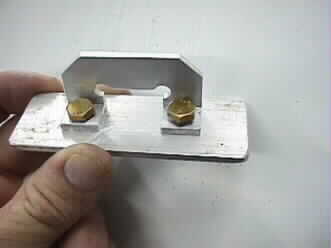
| Here is a slave cylinder piston design that we've used for some years. | Andy Hollit OZ |
| Don't overtorque the undercarriage retaining bolts or they break! Slime the tyres. To repair a flat, carry a spare tube and make 2 spanners to undo the split rims. Bend two 5" lengths of 1/4" square rod in the middle and epoxy a 12mm & 13mm socket (Cash Converters) to each. A12mm/13mm spanner, a pocket screwdriver and a high pressure bicycle pump complete the outfit. |
Andy Hollit OZ |
| Undercarriage aluminium saddles - I found the fit of the aluminium saddles to the legs was poor; the edges just dug in and there was not much more than 'point' contact. To improve matters, I filed the square internal edges off the saddles (don't take too much off!) and then bedded both saddles in with 5-minute epoxy and flock - between the saddle and the leg. I tightened the bolts, but left them about a turn short of fully tight, then tightened up fully after a few hours. This is one of the unsatisfactory elements of the kit's (otherwise good) design, and I believe Jabiru should instruct builders to use this method to spread the load of the retaining saddles to the underside of the legs. I'm sure that now the legs will remain tighter for longer. |
Andy Silvester |
| When I built my Jab I rounded off the edge of the undercarriage clamp where it
contacts the gear leg, as this seemed an area of possible rapid wear. I retightened the
bolts after 10 hours operation and all seems ok since ( 80 hrs). You have to be careful
not to overtighten the bolts because they can shear whilst in operation. To check for
play, apply the brake and lift the wing tip a bit and rock the plane back and fowards. It
should be possible to see the excessive play. Make sure the bolts are not thread bound. You should only have about 2 or 3 threads showing through the nyloc nut. AN6 bolts are used instead of AN5 now |
Vic Leggott |
| The nylock nuts on the rear bolts of the undercarriage are hard to get to, requiring the fuel tank to be removed. However, if these nuts are locked (I used flat "spanner tabs" made out of aluminium, flocked in ) then tightening the bolts is easy. If the brackets have been bedded in as described above, this shouldn't need to be done often though. Thanks for this website! | Bruce Tuncks |
| This is a simple screwjack built around a 75mm high tensile 10mm bolt, running in a piece of chrom moly tube with top and bottom shoulders welded on. A saddle welded to the head of the bolt fits under the undercarriage leg. Turn the nut and up goes the Jabi! | Andy Hollitt |
| When fitting the doors to the fuselage, it will be necessary to heat the doorframe and
bend it to fit flush with the side of the fuselage. It may be useful to put some saw cuts
in the frame of the door to remove the tension and then re-flock. Later kits come with an improved door shape that requires less work. Latest two seat kits have a new design door and frame |
Vic Leggott |
| Door Jam strips (Reffers to earier two seat aircraft) To fit the door jam strips, fit the door and fill the doorframe to get the required even gap. If you pack the door hinge out from the door frame by approx. 5mm this will put the door in about the right position and will require less filler. With the door fitted and the latch in place you can work through the window opening before the window is put in. Feed the jam strip through the window bending and matching the contours of the inside of the door using a hot air gun, clamping every so often to hold in place. Take the strip out and drill for screw holes. Then replace the strip, this time allowing the gap for the draft excluder tape, there should be enough on the reel to cut off 6" to use as a trial fit as you go round screwing it to the door frame. |
Vic Leggott |
| To get a smooth fit from the windscreen to the front top edge of the door, trim the edge of the fitted windscreen to allow the fitting of the door as above. Temporarily screw a 2mm aluminum plate to the inside of the door pillar and with the door shut, mark a line on the plate for the contour of the front edge of the door. Remove the plate and shape the plate to this line, cover with parcel tape and refit. You can now build out from the edge of the windscreen to the edge of the plate with resin flock to give a strong edge. Final shaping can be achieved with filler. | Vic Leggott |
| Secure a 1-inch length of � inch flexible hose to the inside of the door restraint strap where it goes round the edge of the door pillar. If the wind catches the door this will act as a damper. | Vic Leggott |
| Use thin stainless steel (camping saucepan) for a striker plate. Stick foam sealing tape to the door. If stuck around the fuselage frame, entry and exit wears it.Mask hinge tubes before painting. Trial mounting doors to hinges causes paint to flake off. | Andy Hollit OZ |
| A roll of door seal strip is available from RS Components (UK) part number 205 0877 (Black) or 205 0855 (Light Grey). Slightly softer than std stuff but doesn't go wrinkly round the corners of the frame. | Alan Gornall |
| RS components 245 5660 is a neat door handle for lowering into the top of the sticky out bit on the inside of the doors, allowing you to pull closed. Looks great! | Alan Gornall |
| Stall Warner I've added a quick sketch to show how the stall warner goes together - see below There was a change in the stall warner set up a year or so ago. It used to be that the hole in the leading edge with the mesh and tab on the lower edge of the hole, fed in the cavity of the wing leading edge. There was a metal pipe that connected the pvc pipe from the fus. to the wing. The way it is now, is mesh and tab with a funnel connected to a pvc pipe that runs inside the leading edge and right into the fus. See here for a PDF on how to fit the new type |
Vic Leggott |
| Folding wings My folding wing kit required replacement of the 1/4" bore bushes in the wing roots with larger tapered bore bushes. Be aware they are screwed and epoxied in, so cannot be heated & pressed out. To remove, a screwdriver slot was ground across one face with a dremmel 3/4 dia. abrasive disc. The bush was heated with a 100Watt tapered bit soldering iron & srewed out The replacement bushes were reluctant to screw in due to the epoxy re-hardening. Not having a suitable tap, I modified an original bush to make an improvised tap I turned back a couple of thread pitches to form an alignment guide then filed two deep grooves across the remaining threads like a proper tap. After a couple of passes the new bushes could be fitted The new bushes were clamped between two 1/4" nuts on a piece of studding, floxed & screwed in with a spanner. |
John Grant |
| An alternative method to the above is to insert a bolt with a nut on it thro. the old bush and put a nut on the other side. Heat up the bolt with a hot air gun and unscrew the bush. Imediately screw the new bush in with 24hr resin/flock while the threaded hole in the wing root is still warm. Try to ensure that the bush is set inline with the bush in the other spar on the same wing See photos of how the kit looks when fitted | Vic Leggott |
| Inspection and Repair of the Skin to core disbonds on the Wings .. MOD/274/013
It is very unlikely that you will find any disbonds to worry about. The reason that the PFA have issued this advisory is because a kit was delivered with some disbond near the tip on the underside, the disbond was between the foam and the skin. The Jabiru wing has been designed and tested to work with 25% disbonds. The wing in question was well within the limits set in Jabiru's guidance note on checking and repairing dissbonds if found, but wisely the PFA decided to issue the advisory to make sure everyone is aware and checks specifically. One way to check your wings top surface is to pull it outside and let the dew condence onto it, you should see your wing spar and any disbond area will show up. As PFA point out a disbond could occour at any time through various reasons and therefore you should visually check your wings surfaces on check "A" as per any other plane. |
ST Aviation Ltd |
| Rough Guide to Fitting Flaps and Ailerons Make sure all peel ply is removed from the wing before bonding and I suggest keying bonding surfaces with some 60 grit glass paper Cut out the marked area on the top surface of the wing for the aileron (leave a bit on the inboard end of the cut out to trim to fit later). I can't remember the last time I came across a aileron cable exit hole cut out marking in the correct place. You need to check yours with a cable or a pencil/stick and allow for the cable clamp which will space it out from the reinforced mount inside the wing. With the exit hole cut and cable lined up, check the position of the aileron horn. The aileron may need a bit trimming off one end to bring it in line I have found that the lengths of flap and aileron vary from kit to kit and even wing to wing. There is usually a step at the end of the flap and aileron where it is just the thickness of the skin. I usually find you have to cut quite a bit off the inboard end of the flap, to give clearance against the fuselage. The flap rod can have spacer washers to get the alignment of that right. The slot for the flap rod may not be in quite the right place on the flap. I usually make it so the edge of the slot is on the end of the root of the flap where the rod end bolts to. The trailing edge of the wing may need to be reduced in thickness and levelled out by grinding the underside (flap side) edge be careful not to go through and make holes. The flap can now be temporarily clamped into position with the flap arms fitted with bushes and temporary bolts, and the aileron trial fitted to give an clearence gap between the outboard end of the wing / aileron /flap. In some cases the inboard flap arm may overhang the end of the wing under surface. A small amount of trimming of the outboard end of the aileron and flap may be required to move everything along a bit. When the position of the aileron has been determined, the aileron reo. plate and reo. fibre-glass moldings can be flocked and glassed into place. The outboard reo. molding goes right up the end and the other one is set in from the end of the reo.plate by about 1" to allow for the glassing without interfering with the end of the flap. With the plate done, temporarily put the flap back in position and get the gaps sorted out again. It is now time to flock and glass on the flap arms. Use parcel tape on the edge of the flap to stop any surplus resin sticking the flap to the wing. When the resin has gone off on that job you can fit the aileron and hinges. Use the trailing edge of the flap and trailing edge of the wing with the aileron held in position to mark with a marker pen how much to cut off the reo.plate. Make sure the edge where the hinges go on the aileron has been sanded to make it straight and square. Cut away on the mark on the reo.plate and re-try the aileron and mark as necessary to allow for the hinge pin gap and trim. The position for the hinges is governed by where the reo.moldings are. Set them approx. in the middle of the moldings and evenly in from the ends of the aileron. This is a rough guide as wings and moldings do vary between kits and the end result may require different solutions. Use the manual. Wet wings will have some fuel tank fitting work. This write up covers 4 seat and 2 seat kits although flap / fuslage clearance requirements vary. Long wing versions require a pair of top hat bushes on the inboard flap arm. |
Vic Leggott |
| Here are some pictures of the wing folding kit within the text
The flap push rods and aileron cables are detached. The strut has to be removed and the wing tip lowered to the ground. Note that in this position an angle should be cut on the underside of the flap to give clearance against the fuselage. Then the release lever is raised to detach the wing from the fuselage. The wing is pulled out away horizontally from the fuselage and rotated, trailing edge down. The wing can now be taken along side the fuselage and over the tail. Some type of support will be required. If the aircraft is on a trailer, the wing support could be built onto the trailer itself but I wouldn't recommend towing away from the airfield without removing the wings completely. If you intend removing but not folding the wings, then the wing fold kit is still worth considering due to the quick release aspect. |
Vic Leggott |
| When bolting on the wings and struts, the stainless steel bushes that are set in resin
within the fuselage / wing lugs may not be in correct alignment. This can be remedied by
heating up the bush with a soldering iron and carefully reposition it. This should be
checked to prevent incorrect (torsional) loads being applied to the wing attach brackets
and the strut ends. Start off with standard AN bolts for wing and strut attachment and DON'T use close tol. bolts as supplied. These will be tight enough and give you something to change to if wear develops in later years. Do not ream the hole out to fit clos tol. bolts! |
Vic Leggott |
| Don't fully cowl wing stay fittings at wing, leave 5mm exposed for wing tie down rope. | Andy Hollit OZ |
Builders are finding it easier to fit the flaps before the ailerons, as it helps with alignment of the ailerons |
ST Aviation |
| If you are not fitting the wing folding kit, drill a 3/4"hole in the trailing
edge, in the area behind where the leading edge of the flap sits, in line with the wing
attach bolt. This will make it easier to insert the bolt and tighten. Remember to only do up the bolts on the wing attach and strut attach points so that the washer is still free to rotate |
Vic Leggott |
| The tip above 'Remember to only do up the bolts on the wing attach and strut attach points so that the washer is still free to rotate'is quite correct. Too much tension will stress the aluminium forks. But it's been pointed out to me that a vibrating washer WILL actually cut in to the shaft of a bolt (not good when it's holding the wing in place!). Our solutions were to put a dob of Sikaflex on to the washer to hold it steady, or don't use washers. | Andy Hollit OZ |
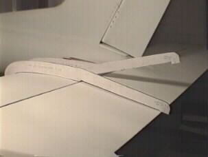
| When first rigged, my Jabiru needed some adjustment to get the incidence angles exactly the same on each wing. To test this, you remove the flaps and put a straight-edge against the underside, taking care to make it parallel to the fuse centreline. Use a plastic tube filled with water and make one end of the straight-edge level with the water surface at the trailing edge, then record the height from the straightedge to the water surface at the leading edge. Repeat with the same position on the other wing. There should be no difference beyond a couple of mm.Do this at several points along the wings.If there is more difference than say 2mm, the factory can supply bushes drilled off-centre, each bush able to correct 2mm. Swapping bushes consists of heating the fitted one with a soldering iron, quickly putting a high-tensile m6 bolt and nut on tightly and screwing the old bush out. The new bush is ground down to the same thichness, cleaned up and screwed in with thin epoxy-flock. | Bruce Tuncks |
| I found the nuts and bolts on the wing fixings too hard to put in, and there was a
risk of damaging the aluminium on the fuselage fittings with the threaded end of the
bolts. So I made tapered-end pins out of 2" long bolts (same diameter) and used
glider-type safety pins as retainers. The wing lugs are within the parallel part of the
pins of course, so there is no change in the strength of the fitting. But rigging and
derigging is now easy, with the pins greased before insertion. This method has been standard glider practice for at least 50 years. |
Bruce Tuncks |
| Radio Noise document click here | Ralph Sanson |
| Jabiru Regulator
In detail, Jabiru charging system uses a PMA (permanent magnet
alternator) which in my day was called a dynamo and the AC output of this
around 30 volts peak is fed to the rectifier-regulator unit. Jabiru use a
full wave switching rectifier and the output is regulated by triggering or
not triggering the SCRs in the rectifier. Once an SCR is enabled to
conduct it will not switch off until the input voltage is reversed. This
results in an output to the DC bus, battery and avionics, of a series of
pulses of varying length and peak voltage up to 30 volts. The set point of
the Jabiru regulator is around 14.8 volts average. This is consistent with
a vehicle start battery recharge cycle. |
Ralph Sanson |
|
ST fuel flow monitor Blank LCD displays Information regarding 'Replacing LCD display' Click here for PDF |
|
|
Some Jabiru owners may also wish to use special antennas built for composite aircraft that are not visible from the outside. i.e. nothing sticks out. I have installed two such antennas in my Jabiru: 1. A COM antenna that is a folded dipole with a feedpoint match that brings VSWR to less than 2:1 across the COM frequency band. It is installed on the left sidewall behind the sound curtain and follows the curvature of the Jabiru fuselage. The antenna requires 12" of fore and aft space and 26.5" vertically. It works very well. One source is Chief AIrcraft in Grants Pass, Oregon 97526, USA Tel. +1-541-476-6605 or Fax: +1-541-479-4431 and is called SA-006 and lists for $78.00. 2. A Transponder/DME antenna which is actually an etched copper clad epoxy board dipole and does not require the usual ground plane other Transponder/DME antennas need. The dimensions are 6" by 7" and I epoxied it onto the right fuselage wall behind the sound curtain in a vertical position. It also works fine and can be purchased from the same source. The part number is SA-005 and the price $78.00. These antennas are designed and manufactured by Archer and I am sure other distributors of avionics also carry them in their inventory. They use standard BNC connectors and the COM antenna is made out of Alclad .016" thick 2024 aluminium strips that allows tuning to a level beyond that of most antennas available today. Best of all they are featherlight and do not protude outside the fuselage skin. |
Karl Geng |
| Jabiru kits now come supplied with a Com antenna which is two sections of flat aluminium rod glassed into the recess in the vertical fin behind the rudder. The top section is already fixed and the lower section is glassed in after the tail has been joined to the fuselage. This performs very well | Vic Leggott |
A jumbo flashing LED wired to the on/off terminal on the oil pressure sender warns of low oil pressure and reminds you to shut off the master switch! Safety flange on the master switch to avoid switching it instead of the fuel pump! One earth point only on the firewall. An earth wire must run from the earth buss to the tank earthing point. Instrument bussbars must be mounted on plastic standoffs to prevent live bolt heads. Mount a 50 Watt anti collision light on the nosewheel leg (Rocca's etc). On all the time. Forget about a strobe, no one will see it, unless you fly at night! But; if you land later than anticipated, mount a Dick Smith swivel torch, Y2154 in plastic conduit to the upper spine behind the crossbeam (where the headsets are normally stored) to illuminate the panel. A red filter will stop reflections off the windscreen and retain your night vision. . |
Andy Hollit OZ |